Arduino – How to get started
Index
When you found my website, I am pretty sure you have already heard about Arduinos.
But what is Arduino anyway?
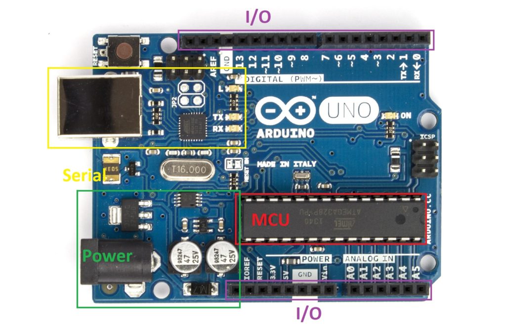
Most of you will probably think of a board like this.

oomlout [CC BY-SA (https://creativecommons.org/licenses/by-sa/2.0)]
However, Arduino is much, much more.
Arduino is a Physical-Computing-Platform consisting of hardware and software.
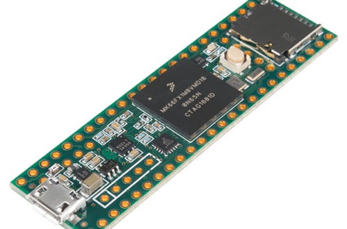
The Arduino Uno Board you can see above is the most common Arduino hardware, but there are numerous other boards. All of them, with their strengths and weaknesses.
Let’s find out what makes an Arduino Board run.
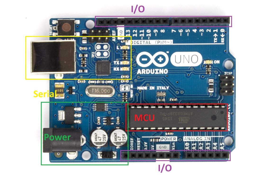
The Arduino Uno consists of four major sections.
Let’s look at them in more detail.
MCU
MCU stands for Microcontroller Unit. It´s the most crucial part of the Board. That’s where the magic happens. All the code you write is stored and executed within this chip. The microcontroller on most Arduino Boards is the Atmega328P, a chip formally produced by Atmel, which was bought by Microchip some time ago. The Atmega328P is an 8-Bit AVR Microcontroller. What that means exactly we will find out in the future.
What’s in there?
An MCU consists of many different parts, cramped together in a single chip. There is the CPU, the Central Processing Unit which is responsible for all the calculations, the RAM (Random Access Memory) for storing the variables used in the programs, the ROM (Read Only Memory) where your application is stored, the EEPROM (Electronic Erasable Programmable Read-Only Memory) used to store variables even when powered down, the GPIO (General Purpose Input Output) for interfacing with the real world, timers for keeping time and knowing when to do what, and much more. If you want to know all your chips’ capabilities, you can always take a look at the Datasheet. In the future, I will try to explain to you what is important and how you can understand these highly technical documentations.
Arduino != (not equals) Arduino
There are a few different models of Arduino hardware. Various sizes, different capabilities, different numbers of I/O pins, different amounts of RAM, and Memory (ROM), …. Most of them are using the same MCU, the Atmega328P, but some of them use different Chips. If you are using another model, then the one I am using in my projects, you have to make sure it is compatible. Some of them, for example, are only capable of handling 3.3V instead of 5V. Soon I will give you an overview of the different models.
The Arduino I use most of the time is either the Arduino Uno. If my project needs a Board with a smaller form factor, instead, I use the Arduino Pro Mini. But here you need an external USB to Serial converter to program and communicate our Microcontroller.
I/O
With the I/O (Input and Output), also called GPIO (General Purpose Input Output), you can interface the real world. Switch on an LED, read a switch, turn a motor, read sensors, make noise, …. Nearly everything is possible here. Sometimes it is just as simple as turn an output on or off, but sometimes, especially when you are communicating with other chips in a different Microcontroller or a sensor, the communication can become quite complicated and challenging.
Let’s get a bit technical
Most of the Arduino Boards work with a 5V(olt) logic level. This means when the output is at full strength, the output has a voltage of 5V. When the output is turned off, the output has a voltage of 0V. Therefore, it is connected to Ground (GND). A 5V logic level also means, if not specified differently, that this is the maximum input rating. If you connect more than 5V to any of the I/O Pins, you can be quite sure to destroy your whole Arduino or at least parts of it.
Analog or digital input?
The Arduino has two different Pin Types for Inputs. Some pins are analog, and some are digital. But what`s the difference? Digital signals can be either on or off. There is no other possibility, whereas analog signals can take many different values. Let’s look at digital signals first.
The digital input
Digital signals are used most of the time with microcontrollers. Computers, in general, work with digital logic. A digital signal can be on or off, just like a switch. By changing between on and off, we can transmit information, calculate something, or read the state of a switch. As stated, the Arduino uses a 5V logic level. Therefore, a Voltage of 5V connected to an input pin is recognized as a logic High or a 1.0V, on the other hand, is known as a logic Low or a 0. All the GPIO Pins can be used as digital inputs.
The analog input
Analog Signals are mostly used to read Sensor information. The difference to digital signals is an analog signal can not only show if there is a signal but also how strong it is. Wow, that sounds way better. Why don’t we always use analog signals? As already stated, computers and microcontrollers, which are also little computers, can only work with digital signals.
So you always have to convert the analog signals to digital signals. This is done with an ADC (Analog Digital Converter). The Atmega328P has a 10-Bit ADC built-in. That means the Arduino reads a signal from 0V to 5V in 1024 Steps. Converting an analog signal costs time and power. And most of the time, you don’t care what the exact signal strength is. It doesn’t matter ‘how much’ a switch is pressed because it can only be on or off, nothing in between.
But sometimes it is important how big a signal is. For example, when you use a potentiometer to tweak a value when you want to measure the temperature or detect how much light is around you. Then it’s worth the time and energy to convert the Value. The analog inputs on your Arduino Uno are labeled as A0 to A5. Again, we have to be careful not to feed the analog input more than 5V to be sure not to damage our hardware.
Outputs – or how to control stuff
After covering the inputs, we can now read from analog sensors and digital switches. But of course, we also want to act. Therefore, we also need outputs. Here we have two options again. Analog and digital output. Wait, that’s not true. All our outputs are digital, but with some of them, we can emulate an analog output.
The digital output
Let’s start with the more straightforward, the digital output. As before with the inputs, digital means we have two different states. On and off. 1 and 0. Our output can be either on or off. When turned on, the Pin is connected to VCC (5V Power) and GND when turned off. It sounds quite simple. But we still have to be careful. An output pin should never be directly connected to Ground because most current you should draw from any I/O Pin is 20mA. Any more current can destroy your MCU. That is not a lot of current. Just enough to light an LED, way too little for even a small motor. If you need any more current, you have to find another solution. Soon I will show you a few possibilities you have to avoid these problems.
PWM – The “analog” Output
Now let’s dive into this ‘analog’ output. As already stated, an MCU can only use and output digital signals. There are Chips capable of generating an analog output from an analog input. They are called DAC (Digital Analog Converter). You can find them, for example, in your Mobile Phone for driving your headphones. The Arduino, on the other hand, doesn’t have such a DAC. Therefore, we can’t directly output an analog signal. But we can fake it. The technique used is called PWM (Pulse Width Modulation). It works by switching the output constantly on and off at a very fast rate. And by changing the on and off time, we can, for example, change the brightness of an LED. The standard PWM frequency of the Arduino Uno is 490Hz. Our LED gets turned on and off 490 times per second. That’s so fast we can’t see the LED flickering, but because it’s not lit all the time, it’s visibly darker.
As you can see in the picture, we can change the on and off time, the duty cycle. The Atmel328P uses an 8-Bit value to determine the duty cycle. Therefore, there are 256 different intensity settings. A value of 0 corresponds to a duty cycle of 0% active and, therefore, an output of 0V. On the other hand, a value of 255 corresponds to a duty cycle of 100% or a constant 5V output. You can use the PWM technique to solve many problems quickly. The intensity of an LED can be changed, or with a little bit of side circuitry, we can run a motor with variable speed. Not all pins are capable of generating a PWM output. You can identify the PWM capable pins by the ~ Symbol.
Serial converter
I won’t dive very deep int this topic for now. The Serial communication will be the topic of a whole new article. But still a short comment, as this part of the board, is used as a communication bridge between the MCU and a Computer. This way, you can write a program in the memory of the MCU and establish a data connection to receive information from the running program or write data to the device to control its behavior. Just as a debugging tip, if the data you receive either only contains strange symbols or you receive nothing at all, you should check your BAUD rate. That’s the speed at which the Arduino talks to the PC.
Power supply
When connecting the Arduino to a computer over USB, this cable is also used for powering the board. However, you can also power your Arduino from another source, especially when you don’t need your computer, or your project requires more than the 500mA provided by the computers USB ports. One possibility of supply power is the use of a power bank. But there you have to be careful because, if your project doesn’t require much current, it happened to me that the power bank shut off because it couldn’t see enough current draw.
No 5V on hand?
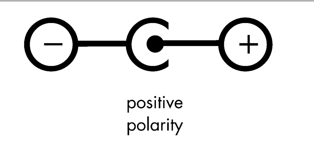
Another option is to power your board through the 2.1mm barrel jack. Because the board provides a linear voltage regulator, the recommended input voltage is between 9V and 12V. The polarity is essential here. The outer ring needs to be the minus, and the inner hole is for the plus pole. You can also feed power to this regulator without using the barrel jack. Therefore you have to connect the power directly to the VIN Pin in the I/O section. The minus pole of the power supply has to be connected to the GND pin.

Three-quarter-ten [CC BY-SA (https://creativecommons.org/licenses/by-sa/3.0)]
You still want a different power source?
If you already have another power supply with a 5V output, you can also power your board directly with the 5V pin in the I/O section. There is no voltage regulate so you must be careful with the voltage. If you accidentally connect 12 volts to the 5V pin I can promise you, you will need a new Arduino. Also, don’t forget to also connect your GND pin.
Conclusion
Even though this was quite a long and sometimes maybe a little bit complicated or even intimidating post, I wanted to give you an overview of the things you see when looking at your newly bought Arduino Uno. And even when you have a different model or even a little experience you hopefully learned at least a little bit. Some of the things you might not need from the start but hopefully, you remember some of the details when you are sitting in front of your project and have absolutely no idea why this is not working or how to tackle the problem you ran into.
Quite often I said you have to be careful. But in the end, as long as you stay far away from mains power, working with Arduino projects is most of the time quite safe for you. So the only one who really is in danger is your Arduino. But that’s totally fine. Sometimes it happens that you destroy some components. But thankfully the hardware isn’t that expensive. Since beginning with my hobby, I have killed many components and quite a few Arduinos too. But you shouldn’t see things like that as a setback. Mistakes happen. But still, I am trying to help you along the way to maximize the fun and minimize the frustration. Have fun and keep fighting!


One Comment
Pingback: